South-Korea (한국어)
South-Korea (한국어)
A horizontal orientation is recommended for most thermoforming tools.
Resource Guide

FDM thermoforming design guide

1 Introduction and background

1.1 Scope

This technical design guide describes the design, processing, manufacture, and post-processing techniques and procedures for additively manufactured thermoforming tooling using Stratasys FDM® technology. The principles discussed and requirements provided in this guide for part creation and implementation should be followed whenever possible. Due to the various thermoforming industry best practices, deviations to this design guide may be implemented at the discretion of the individual user’s expertise.

1.2 Application overview

Thermoforming is a manufacturing process for forming thermoplastic sheets or films over a mold through the application of heat and pressure. In this process, a sheet is first clamped and heated to the sag point (above the glass transition temperature [Tg] of the polymer), usually by a radiant heating source, and then forced against a mold surface produced by FDM through the application of a vacuum source or air pressure.

1.3 Background and purpose 

Traditionally, thermoform tooling has been made from wood, RenShape board, cast aluminum or machined aluminum billet. Although these legacy techniques are still relevant today, the high cost and long lead times of these methods are leading thermoform part manufacturers to seek new tooling solutions for low- to moderate-quantity production runs. The need for a solution that lent itself to low-volume thermoforming batches as well as complex shapes led Stratasys engineers to investigate the feasibility of additively manufacturing thermoforming tools to reduce tooling costs, material waste and long lead times. 

A rigorous series of lifecycle testing occurred using ABS and Kydex thermoforming materials formed over additively manufactured tools. Pairing these thermoforming materials with additive manufacturing materials including acrylonitrile styrene acrylate (ASA), polycarbonate (PC), and ULTEM™ 9085 resin (a polyetherimide [PEI] blend), led to a better understanding of the design criteria needed to meet specific application needs from various industries such as aerospace and automotive. Criteria included sheet draw ratios, transient convective and conductive heat transfer during the thermoforming process, and tool heat dissipation rates that affect the tool wear and tolerances over time due to thermoplastic warp and thermal shock. Understanding FDM tool performance led to the development of best practices for using additively manufactured tools versus traditional subtractive methods, highlighted in this guide. 

This design guide provides best practices for the design, fabrication and preparation of additively manufactured thermoform tooling, as well as relevant performance characterization data.

2   Industry relevance and benefits

The six fundamental drivers of additive manufacturing listed below were assessed to determine how additive manufacturing improves tooling for thermoforming applications.

2.1 Economic low-volume production

The cost of tooling for subtractive-based manufacturing methods has been expressed as a concern from partners in various thermoforming markets including aerospace and automotive. The need to increase the return on investment (ROI) in a competitive production environment is highly prized. Additive manufacturing takes advantage of just-in-time manufacturing principles that allow the economic production of low volume and one-off designs.

2.2 Life cycle sustainability

Whether it is through good corporate social responsibility, legislative compliance or an understanding of environmental good practice, thermoforming companies are beginning to focus more on their environmental impact. But this is not limited just to the impact of the initial production tooling, but the impact of their products during and after their effective working life.

Additive manufacturing is used to reduce the life-cycle environmental impact of products in a number of ways:

  • Additive manufacturing processes can be highly material efficient, using only the minimal material needed to make a part, with little waste. This differs greatly from processes such as machining, which rely on billets of feed stock, often largely reduced to scrap.
  • As a digital-based technology, additive manufacturing can also be used to position material only where material is needed, making parts that have the perfect balance of strength and weight. Again, reducing the amount of raw material needed to drive the supply chain, but also the amount of energy needed to make the part.
  • Parts with an optimized strength-to-weight ratio have a life-cycle environmental benefit, as part consolidation aids in reducing the overall amount of tooling needed for each program. For instance, shipping distances can be reduced through a distributed manufacturing environment and the reduction of end of life and last-time component buys.


2.3 Increased part functionality

The ability for inherent uniform and localized porosity through the FDM tool provides unique capabilities to draw vacuum through the tool and eliminates manually needing to create vacuum features with traditional methods.

2.4 Supply chain realignment

Stratasys makes it easy to evaluate the technology to ensure it fits in a unique manufacturing environment. Stratasys Direct Manufacturing™ can produce FDM thermoform tooling to ensure the capability meets the specific application requirements. Increasing production throughput justifies printing in-house as a means to reduce tool cost.

2.5 Cost effective product customization

Increased complexity comes at little cost vs. the overall size of the tool, allowing engineers and designers to consider the end product’s key characteristics, not the process that creates the tool.

2.6 Increased product complexity

Tool complexity, in addition to holding tolerance over the lifecycle of the tool, is important in thermoformed parts. Complexity, including gradient features, variable wall thicknesses of the tool to better control the thermal gradient of the tool, internal lattice structures to reduce thermal mass, non-linear design freedom, and the ability to consolidate assemblies allows for the production of thermoforming tools that meet the needs of each specific application.

Incumbent technologies cannot replicate all of these characteristics in a single technology. Traditional methods used to manufacture thermoform tooling are well suited for large-volume production runs, but in a high-mix, low-volume market, FDM thermoform tooling remains advantageous to meet unique applications and requirements.

3   Design overview

3.1 Design guide objectives

The objective of this design guide is to provide best practices for the manufacture of FDM tooling for thermoforming. The intent is to aid in bridging the knowledge gap between design-for-additive-manufacturing techniques and conventional thermoforming best practices.

This design guide aims primarily to provide:

  • Key properties and characteristics for relevant materials
  • Advantages and key considerations for FDM tooling
  • Best practices for design, construction and optimization of form tooling
  • Best practices for file preparation, processing and fabrication
  • Best practices for post-processing form tools
  • Tool life and characterization data


3.2 Key design considerations

The key design considerations are intended to be used as references or starting values and do not guarantee success if the tool is designed within these values, nor failure if the tool is designed outside of these values.

CONSIDERATION VALUE
Male draft angle 3-4 degrees
Female draft angle 2-3 degrees
Minimum radius 0.050 in. (1.27 mm) or thickness of sheet
Maximum areal draw ratio 3:1 part draw ratio
PC CTE 3.80x10⁻⁵ in/in/°F (6.84x10⁻⁵ mm/mm/°Cv)
ULTEM 9085 resin CTE 3.67x10⁻⁵ in/in/°F (6.61x10⁻⁵ mm/mm/°C)
ASA CTE 4.90x10⁻⁶ in/in/°F (8.82x10⁻⁶ mm/mm/°C)
Preferred joint type for sectioned tools Lap joint


Table 1 - Key Design Considerations.

4   FDM materials

Three FDM materials with varying heat-deflection temperatures were tested for use as thermoforming tools. Polycarbonate (PC) and ULTEM™ 9085 resin were successful in testing whereas ASA did not perform adequately and is not a recommended material for use in thermoform tooling.

4.1 ASA

Thermoform tooling made from ASA is not recommended. A 0.125 inch (3.175 mm) polystyrene sheet was formed at 325 °F (163 °C) over an ASA tool and resulted in the top of the tool softening and being pushed down into the sparse structure inside of the tool by the vacuum force on the surface of the tool, as seen in Figure 1.

Additional cap layers were added to the ASA tool in an attempt to prevent sinking of the top layers into the sparse cells. Testing the tool with additional cap layers resulted in no sinking, but the top layers of the tool melted and bonded to the formed part, resulting in extreme difficulty to remove the formed part and damage to the tool. No further testing was performed on ASA tools as the majority of heavy-gauge thermoforming materials are formed above 325 °F (163 °C). ASA may work for lower temperatures or thinner gauge materials, but it is recommended that a higher-temperature FDM material is used.

4.2 PC

PC produced favorable results as an FDM tooling material while forming ABS sheet stock. A total of 223 ABS parts were formed at 360 °F (182 °C) over a PC tool (Figure 2) with a 2 minute, 30 second cycle time. The tool remained in tolerance (less than 0.010 inch [0.254 mm] total deviation) during the forming process for the 223 cycles before drifting out of tolerance (see Section 10 – Cycle Testing Results, for detailed data). A PC tool is recommended for materials that are formed at or below 360 °F (182 °C) and have a cycle time similar to or longer than 2.5 minutes, and for quantities of fewer than 225 parts if tolerances less than 0.010 inch (0.254 mm) are required.

PC was also tested for compatibility with Kydex, which produced less favorable results. A 0.188 inch (4.78 mm) Kydex sheet was formed at 400 °F (204 °C) over a PC tool with a 3 minute 20 second cycle time. The cap layers of the tool heated to over 260 °F (127 °C) according to the embedded thermocouples after six cycles. This heating resulted in softening of the cap layers, which then sank into the sparse cells. Figure 3 shows the “waffling” pattern that occurred on the tooling face as a result of the top layers of the tool softening as well as a comparison of the tool after six cycles to the initial tool. The scan shows a positive deformation around the tool edge of ~0.050 inch (1.27 mm) as well as a negative deformation of ~0.025 inch (0.635 mm) in the center of the tool for an overall tool deformation of ~0.075 inch (1.91 mm).

A PC tool is not recommended for forming Kydex or other materials that exceed a forming temperature of 360 °F (182 °C). ULTEM™ 9085 resin is the recommended FDM thermoforming tool material for these highertemperature materials.

4.3 ULTEM 9085 resin


Kydex was formed over an ULTEM™ 9085 resin tool to determine if ULTEM™ 9085 resin could withstand the highertemperature forming materials. The tool successfully formed 23 Kydex parts at 400 °F (204 °C) with a 3 minute and 20 second cycle time. Figure 4 shows the tool forming Kydex. The tool reached a maximum temperature of 260 °F (127 °C) during the forming process and remained within 0.005 inch (0.127 mm) of the original scan (see Section 10 – Cycle Testing Results, for more detailed data).

5   Tool design

Thermoforming tool design for FDM is similar to designing tools for conventional manufacturing methods for most design features including draft angles, corner radii and draw ratios. Coefficient of thermal expansion (CTE), thermal conductivity and inherent porosity of the FDM tool are factors that should be taken into account during the design process as they differ from traditional materials and tooling methodology.

5.1 Draft angles

Draft angles are designed into the tool to facilitate removal of the thermoformed part. When the formed part cools over the mold, the part (and tool) shrink relative to their respective CTE values, which can cause difficulty removing the part. Incorporating draft angles into the mold promotes easier removal. Standard draft angles for male portions of the tool used with traditional mold design (3-4 degrees) should also be used when designing an FDM mold (Figure 5).

Smaller draft angles can be used on female areas of the tool. When the thermoformed part cools, it shrinks away from the sidewalls of the cavity, promoting removal. Standard draft angles of 2-3 degrees should be used for female portions of the mold.

5.2 Radius and draw ratio

Radius and draw ratio considerations when designing a tool for FDM follow similar principles as designing for traditional methods to prevent thin regions in the thermoformed part. These aspects of tool design depend on the type and thickness of the material being formed rather than the mold design. Standard values for these design criteria are listed in Table 1 - Key Design Considerations.

5.3 CTE

The CTE of FDM materials is typically much higher than that of traditional tooling materials such as aluminum and is an important consideration during tool design. This CTE value must be taken into account when designing the tool such that when the tool reaches an elevated, steady-state temperature during the forming process, the expansion of the mold meets the desired part tolerance. The CTE values for the FDM thermoforming materials discussed in this guide are listed in Table 1 - Key Design Considerations.

5.4 Sectioning

Tools that are larger than the build chamber must be sectioned into multiple components. Sectioning the part in CAD, using a lap joint, is the recommended method. A lap joint ensures proper surface area for bonding. Other joints such as dovetail, tongue and groove, and butt joints may be used as required by the geometry. Figure 6 shows a tool sectioned to demonstrate the use of a lap joint for connecting sections, post-build.

The geometries shown in Figure 6 use a 0.100 inch (2.54 mm) thick lip for the joint to provide adequate space for toolpaths and ensure the lip will not be damaged during assembly or forming operations. A 0.100 inch (2.54 mm) thickness is typically used for FDM lap joints, but may vary depending on geometry or bonding requirements. It is recommended to use a total clearance of 0.010 inch (0.254 mm) (0.005 inch [0.127 mm] around the perimeter of the joint and each face) between the joined components to allow room for adhesive and for the components to easily slide together as shown in Figure 7. Bonding methods for sectioned tools are covered in Section - 7.3 – Bonding Sectioned Tools.

5.5 Porosity

FDM parts are naturally porous and porosity can be increased with sparse processing parameters. Sparse parameters increase the air gap between internal rasters to create an internal cell structure that reduces the density of the part. Natural porosity is beneficial for thermoforming as it eliminates the need for secondary processes to introduce air channels into a tool for airflow. The porosity induced by the standard processing parameters is adequate for most geometries, but additional porosity can be introduced in the tool through the custom groups menu in Insight™, the FDM pre-processing software, for specific features such as deeper draws that require a higher rate of air flow to fully pull the sheet into the cavity. See Section 6.3.1 – Air Gap, for details on how to increase the porosity of a tool.

Custom density can also be designed into tools to increase airflow and reduce material use. Figure 8 shows a tool that has been designed with a custom, tailored density pattern. The tool in Figure 8 was built on its side in the XZ plane and the increasingly dense cell structure at the top of the tool will allow the top face of the tool to bridge without issue. The benefits of designing a tool in this way include material conservation, decreased build time and increased airflow through the tool.

5.6 Mounting holes

If needed, mounting holes should be added after the tool design is complete. These mounting holes will allow the tool to be fastened to the thermoforming apparatus to hold the tool in place while the formed sheet is being released. An adequate number of mounting points must be used to prevent the sheet from pulling the tool off the thermoforming box. Four 0.25 inch (6.35 mm) mounting holes were used for the tool shown in Figure 9. To prevent anomalies on the formed part, countersunk holes were used to keep the fasteners flush with the surface of the tool. Additional material can be added around the mounting holes when processing in Insight to increase the strength in these areas. Insight processing of mounting holes is covered in Section 6.3.2 – Additional Contours around Mounting Holes.

6   Insight processing

Insight is the pre-processing software that imports the .stl file and exports the .cmb file that controls the Fortus® 3D Printer to build the tool. Material, machine and slice-height selections are designated in Insight as well as build orientation and toolpath parameters, which control how the tool is built. The following sections on Insight processing assume a basic knowledge of Insight. See the Step-By-Step Insight Processing Procedure best practice for Insight assistance. Processing parameters such as build orientation, slice height and desired material should be designated on engineering drawings if the tools are being processed and produced externally to ensure the service provider builds the tools as desired.

6.1 Select modeler parameters and import part

PC and ULTEM 9085 resin (recommended thermoforming tool materials) are available on Fortus 400mc™, Fortus 450mc™, and Fortus 900mc™ 3D Printers. Select the desired modeler and model material in the Modeler Setup menu, located under Modelers, Setup before importing the .stl file format into Insight (Figure 10). The slice height of the build should also be chosen at this point. A larger slice height will decrease build time at the expense of surface quality. A smaller slice height will improve surface quality, but will increase overall build time. A 0.010 inch (0.254 mm) slice height is recommended for most thermoform tools as it provides a good combination of surface quality and build time. Import the thermoforming tool .stl file using File, Open.

6.1.1 Importance of build orientation

The build orientation of the .stl file is extremely important. Build orientation will affect the speed of the build, the amount of support material required, the quality of surface finish and the overall performance of the tool. The final tool design intent and requirements must be considered when orienting the part to incorporate surface finish, build time and other aspects affected by orientation. Slice the .stl file after the desired build orientation has been selected. Examples of three varying orientations are described in the following sections.

6.1.1.1 Flat (XY)

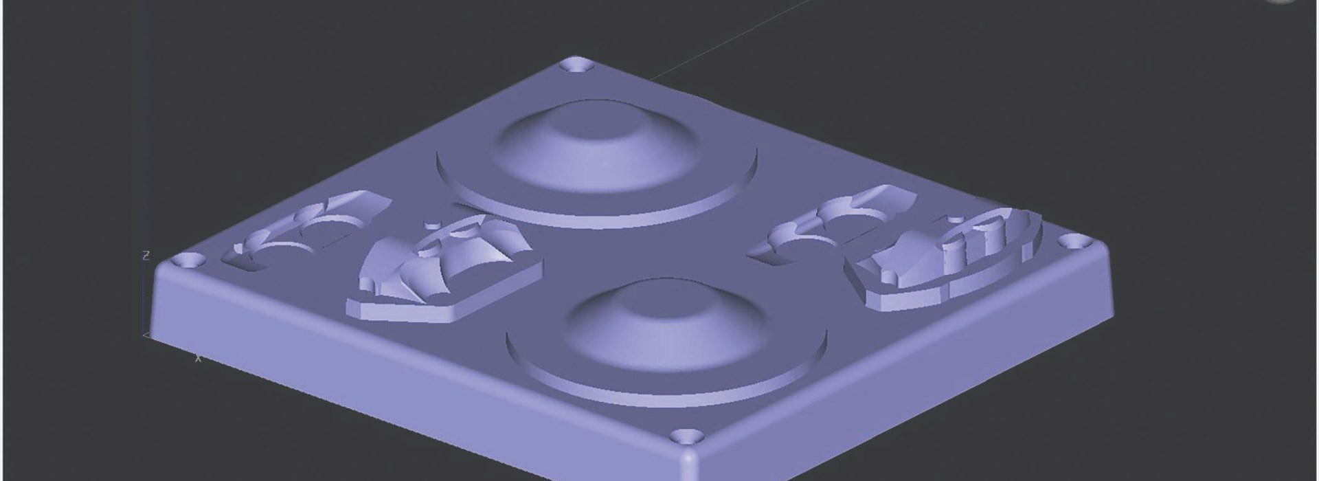
The flat or horizontal orientation in the XY plane is recommended for most thermoforming tools. A horizontal orientation is shown in Figure 11. The flat orientation provides the tool with sufficient vacuum to the inner tool surfaces while generally being faster to print, including the areas for tool run-out.

This orientation can result in a sub-optimal surface finish for this specific geometry due to stairstepping on gradually sloped faces. Stair-stepping or exaggerated layer lines are shown in Figure 12 and can require more in-depth post-processing compared with the vertically oriented tool to achieve adequate surface finish.

6.1.1.2 Vertical (XZ)

A vertical orientation with the tool in the XZ plane, shown in Figure 13, is recommended for tools with high surface finish requirements that would be stair-stepped if built horizontally. The vertical orientation will generally take longer to print due to the increase in Z-height but will require less post-processing to achieve a smooth surface finish and still permits sufficient airflow through the vertical tool face to draw down the formed sheet. A vertical orientation should also be used for tools with designed porosity as this orientation takes advantage of self-supporting angles and reduces the amount of support material needed. Figure 13 shows the orientation of a tool with tailored density.

6.1.1.3 Other orientations

When a tool does not have a simple geometry that can easily be printed in vertical or horizontal orientations, or when these orientations result in undesirable surface finish, the tool can be alternatively positioned in the build space to achieve the desired surface finish. Figure 14 demonstrates an orientation where the tool is rotated up at 45 degrees about the Y-axis. A 45 degree orientation yields a better surface finish due to reduced stair-stepping and minimizes the amount of support material needed by utilizing self-supporting angles. This custom orientation will require a stabilizer wall to be added to the back side of the tool to prevent it from tipping over during the building process (stabilizer walls are covered in Section 6.2.1 – Stabilizer Walls). To achieve the on-edge orientation seen in Figure 14, the rotation menu shown in Figure 15 can be used. The X, Y and Z angles displayed are absolute references to the original, imported orientation. To incrementally change the orientation, input the degree change and click the individual axes rotate buttons. Improving surface finish and decreasing build time and material use are the main considerations to review when orientating a part for FDM thermoform tooling.

6.2 Generate supports

Generate supports once the file has been oriented and sliced. Minimizing the amount of support will reduce the build time of the tool. It is also recommended to attempt to reduce or eliminate supports on faces of the tool that will come in contact with the thermoformed part as reduced surface quality occurs at support interfaces of the tool. ULTEM 9085 resin uses a breakaway support material only and PC has the option of either a breakaway or soluble support. Breakaway supports must be removed by hand and design considerations need to be taken to not trap supports in deep cavities, channels or holes. Breakaway support removal is aided by the default support parameters (basic for PC and sparse for ULTEM 9085 resin). The soluble support option for PC dissolves in a detergent bath, which allows for support removal from difficult areas but requires the tool to be dried after support removal as the liquid will collect in the sparse cells of the tool. Default support settings are recommend when generating supports for thermoform tooling.

6.2.1 Stabilizer walls

Thermoforming tools that have tall designs with a small footprint on the build sheet may require additional support to enhance stability and prevent build failure. Stabilizer walls are typically only needed with tools being built in vertical or nonstandard orientations. Stabilizer walls are singlebead structures that slightly penetrate into the tool to help stabilize it during building, shown in Figure 16. The stabilizing structures can easily be removed after the build due to their perforations, similar to a perforated piece of paper.

A top-down view of a stabilizer wall and specific design details are shown in Figure 17. Parameters not detailed are recommended to be left as default.

  • The Separation value controls how far the back of the wall is separated from the tool
  • The Contact interval value controls how much distance is between each contact leg of the stabilizer wall.
  • The Penetration value controls how deep the wall penetrates into the tool.
  • The units of these values are the same as the units selected within Insight (inch or mm).


6.3 Non-standard toolpath generation

Generate toolpaths after support structures have been created. Default sparse toolpath settings are recommended for both PC and ULTEM 9085 resin for thermoforming applications. If necessary, air gaps may be increased to facilitate airflow through the tool. This is covered in the following section. Additional custom toolpath modifications can be found within the Custom Groups in Insight best practice document for custom toolpath generation.

6.3.1 Air gap

The air gap between adjacent rasters, or the sparse raster air gap under the custom groups menu (Figure 18), can be increased to induce additional porosity. Increasing the air gap between adjacent rasters will add an air gap between rasters on cap layers. It is recommended to only increase the air gap between adjacent rasters up to 0.003 inch (0.076 mm), or visible holes may appear in the surface of the tool that will transfer to the formed part. Adding specific layers to a custom group is shown in Figure 19 and adding the entire part to a custom group is shown in Figure 20.

Increasing the sparse raster air gap increases the size of the sparse fill cells and will reduce build time and tool strength. Caution should be used when increasing this value from the default as the cells can become too large and the cap layers will not be able to bridge the cells on flat surfaces of the tool as can be seen in Figure 21.

6.3.2 Additional contours around mounting holes

Additional material around mounting holes is recommended to increase the strength of the holes. More material can be achieved by increasing the number of contours around the holes in Insight using a custom group. Create a new custom group using the same parameters as the global parameters, change the number of contours to the desired amount, and check the Apply contour style to selected feature only box as show in Figure 22. The check box ensures that the extra contours are only added to the selected mounting holes and not the entire part.

Add the curves that make up the mounting holes to the custom group. Only the selected features will be in a custom group as shown in Figure 23. The figure also shows the resulting toolpath generation from the custom group.

6.4 Seams

A seam is defined as the start and stop location of a toolpath, as shown in Figure 24. A seam can potentially cause a blemish in the final part if the tool surface in contact with the formed sheet contains seams. Placement of seams is important when processing in Insight for this reason. Seams should be placed on a part of the tool that will not contact the formed sheet, on the least important side of the tool, or on a face where they can easily be smoothed by light sanding after the tool has been built. Seam placement on the part can be changed under the Toolpaths, Seam control menu.

6.5 Save .cmb file

Once all supports, toolpaths and custom groups are satisfactory, generate toolpaths and save the job, creating a .cmb file. The .cmb file is then packed in Control Center™ and sent to the 3D printer for production.

7   Post-processing

7.1 Sanding
Tool faces have a patterned texture from the layer deposition process. These layered textures, which could consist of stair-stepped surfaces, a texture on a vertical wall from layer stacking, a texture on a flat face caused by toolpath deposition, or a combination of these, will transfer to the thermoformed part where it contacts the tool and may cause the formed plastic sheets to adhere to the tool walls, making the removal of the formed part difficult. Sanding is recommended for critical surfaces that require an improved surface finish and for extruded areas where the sheet needs to flow over the tool (Figure 25). The sanded surfaces will facilitate easier de-molding of the formed part as well as an improved surface finish. When sanding, care must be taken to maintain dimensional accuracy of the tool.

7.2 Sealing
7.2.1 Side walls
The vertical side walls of the tool will have layer lines and porosity that allows airflow through the walls. Sealing the vertical surfaces with epoxy will eliminate the airflow through these surfaces, preventing the formed sheet from pulling into and “grabbing” the layer lines, which will hinder material flow over these areas of the tool. Further sanding after the epoxy application is recommended to attain a smooth surface finish on the walls.

7.2.2 Top surfaces
Extruded top surfaces are sealed for similar reasons as side walls. Top surfaces will have raster and contour lines that increase likelihood that the formed sheet will not flow properly over these extrusions. In addition, the surface will naturally allow vacuum to pass through the surface and the formed sheet may pull into the toolpath lines and hinder material flow over these areas, which can cause thicker sections on the tops of the extrusions and thin areas on the sides of the extrusions. Epoxy may need to be applied to these surfaces to promote flow and obtain a more uniform formed sheet thickness. Sand as needed to attain the required surface finish after the application of epoxy (Figure 26).

7.3 Bonding sectioned tools
Tools that needed to be sectioned can be joined together using the methods described in the Technical Application Guide: Comparison of Bonding Methods for FDM Materials. The recommended bonding methods for thermoforming are epoxy bonding, hot-air plastic welding or a combination. Figure 27 shows the bonding process. A layer of epoxy is applied to the inside of the female mold and the parts are slid together. Any excess epoxy is wiped clean and the seam is then hot-air welded to fill the mating seam. The welded seam is sanded to create a seam that is smooth with the rest of the part and will not be seen on the formed parts. The epoxy and hot-air welding will reduce the amount of vacuum along the seam; therefore, it is recommended to place the seam in an area where less airflow is needed to form the part.

8   forming

The standard forming procedures used for traditional tooling are also used for FDM tooling (Figure 28). Cycle times may need to be adjusted slightly to ensure that the FDM tool has enough time to cool between cycles as FDM materials are not as thermally conductive as some traditional tooling materials, such as aluminum.

  9 Trimming


The thermoformed part should be trimmed after forming to remove the excess plastic sheet that surrounds the molded part. A trim method must be selected and corresponding jigs, fixtures, dies and toolpath programming must be produced.

9.1 Trimming
Methods A thermoformed part can be trimmed using various methods, including hand trimming, shearing with dies, CNC machining and laser trimming. Each method has advantages and disadvantages to consider.

Hand trimming uses knives, saws or routers operated by hand to trim the excess plastic from the part. Hand trimming is advantageous for short runs as it does not need complicated dies, fixtures or machine programming. This method does require a person to operate the tools and typical safety precautions for operating the tools must be taken. A trim tool can be designed to guide the cutting tool to decrease the time to trim the parts and increase the consistency of the finished parts. Trim tools can be produced with additive manufacturing to minimize lead time.

Die trim methods use a hardened, sharpened steel punch in the shape of the perimeter of the part and the die is pressed through the plastic and into a mating die. This method offers repeatability, consistency and a quick cycle time for trimming but the initial die and maintenance can be expensive depending on the selected die method.

CNC machining uses a multi-axis machine to trim the part and may be semi or fully automated. The machine is programmed so that the cutting tool follows the desired path. The cutting bit must be selected for compatibility with the plastic. This method offers accuracy, consistency and reduced labor, but requires machine availability, the cost to program the machine, and often additional fixtures to hold the part during machining.

Parts can be trimmed using a high-powered laser. This method produces accurate parts with clean edges. The laser also provides versatility to trim different shapes, but it must be programmed to trim the shape of the parts and the machine is generally more expensive to purchase and maintain.

9.2 Trim Tool Design for Hand Trimming
The purpose of creating a trim tool is to provide a guide for hand-operated cutting devices to increase the speed and consistency of the trim. The consistency and accuracy of the trimmed edge directly correlates to the design of the trim tool. To design the trim tool, one must have first selected the handheld cutting device and have the dimensions of the part that will be trimmed. Images are included from the design of a trim tool for a handheld rotary cutter and an oscillating cutter. Figures 29 and 30 show the complete trim-tool designs.

First, determine what features of the handheld cutter can interface with the trim tool or if an additional part is needed to guide the device. For example, the shaft between the blade and the handle of an oscillating tool may be able to guide the cutter against the trim tool, but a rotary cutter may need a part that can be screwed onto its threads. Figures 31 and 32 each show the head of the cutting tool used for the trim-tool design. The rotary cutter attachment was designed so that the two smaller-diameter sections would follow the trim-tool track to guide the cut.

Determine the desired location to cut the part; depending on the design intent of the formed part, it could be on the vertical sidewall of the part, the flat excess plastic surrounding the part, or the radius where the sidewall and flat plastic of the sheet intersect, as shown in Figure 33. Determine the orientation of the cutting tool needed to trim the part at the desired location and which features on the cutting tool will be used as guides to cut the thermoformed part at the desired location. Be mindful of the length of the cutting edge and what clearance there is on the other side of the tool when cutting through.

A swept feature using the perimeter of the part to be trimmed was the initial feature to begin the design of the trim tool. The thickness of the plastic sheet must be taken into account when designing the trim tool from the thermoforming tool to ensure a proper fit. The fit of the trim tool to the thermoformed part is critical as it affects the consistency and location of the trimmed edge. The profile for the swept feature is the part that will be able to guide the cutting device. Design the profile with features to guide the cutter in the proper position to cut the part at the desired location. Figure 34 shows the profiles that were used for the trim tool designs in this guide.

Additional features can be added to the trim tool after the main profile has been created. Needed features will vary by the selected cutting tool and geometry of the formed part. These features may include the following:

  • Stops for the cutting tool: A stop may be used to stop the cutting tool before the cutting edge intersects the trim tool. Figure 35 is an example of a stop used with the oscillating cutter that prevents its blade from being pushed too far and into the trim tool.


  • Alignment features to hold the thermoformed part:Features should be added to the trim tool that hold the formed part at the needed location while trimming. The fit of the trim tool to the thermoformed part affects the consistency and location of the trimmed edge. Trim tools for symmetric thermoformed parts should offset alignment features on each side so the trim tool can be rotated by 180 degrees to trim the sections where these features initially prevented trimming of the edge. Figure 36 shows the alignment feature used to hold the thermoformed part in place within the trim tool for the oscillating cutter.


  • Connecters between two parts of a swept feature: A connector is needed to hold the two parts of a swept feature together if the cutting tool must go through the feature as shown in Figure 37. Without connectors, the trim tool would be two separate pieces. Connectors should be offset on opposing sides for symmetric parts so the trim tool can be rotated to trim the regions previously blocked by the connectors.


  • Ramps to ease the cutting edge into the plastic: A ramp can be added for bladed cutting tools, such as the oscillating tool, to guide the blade into the plastic at the beginning of the trim motion. Figure 38 shows the ramp used for the oscillating cutting tool.


  • Chamfers and fillets: These can be added to remove any sharp edges on the trim tool and finish the part.


The trim tool can be additively manufactured on the same machine that produced the thermoforming tool. The finished trim tools for the oscillating and rotary cutters are shown in Figure 39.

10    Cycle testing results

10.1 Overview

A PC tool was used to form 223 ABS sheets of 0.118 inch (3 mm) thickness before tool tolerance drifted more than 0.010 inch (0.254 mm). The ABS sheets were formed at 360 °F (182 °C) with a 2.5 minute cycle time. Thermocouples were embedded into the tool in four places of varying geometry to observe the temperature of the tool during the forming process. The tool was scanned using a Creaform laser scanner (accuracy of 0.0015 inch [0.038 mm] for the tool used for cycle testing) at various intervals (18 hits, 123 hits, 223 hits, and 285 hits) and compared with a baseline scan of the unused tool to observe deformation and degradation.

An ULTEM 9085 resin tool was used to form 23 Kydex sheets of 0.188 inch (4.78 mm) thickness to reach a steady state temperature with the tool and to validate higher-temperature forming materials. The Kydex sheets were formed at 400 °F (204 °C) with a 3 minute and 20 second cycle time. The ULTEM 9085 resin tool also had four thermocouples embedded within the tool to observe temperature profiles during the forming process and was scanned with the same laser scanner at four hits and 23 hits to observe tool deformation.

10.2 Temperature Data

10.2.1 PC Tool Forming ABS Thermocouples were embedded in the PC tool using an epoxy with similar thermal conductivity to the plastic at the 4 locations shown in Figure 40. Number 1 was placed 0.020 inch (0.508 mm) below the surface of the tool at the highest point of tool in the small boss. Number 2 was placed 0.020 inch (0.508 mm) below the surface of the tool in the lowest cavity of the part.

Number 3 was placed in the center of the tool 0.25 inch (6.35 mm) below the surface to monitor internal temperatures, and number 4 was placed 0.020 inch (0.508 mm) below the surface at the top of the cone.

Temperature profiles for the thermocouples of the PC tool while forming ABS are shown in Figure 41. The temperature profiles demonstrate the forming cycle. Starting from an initial temperature, the tool heated dramatically at the beginning of each cycle when the hot sheet initially made contact with the tool (each spike on the graph represents the beginning of a new cycle). The tool then cooled for the remainder of the cycle as the part was cooling and being released from the tool. The tool continually increased in maximum temperature during each cycle until a steady state was reached after roughly five cycles. The steady state temperature of the tool remained below 220 °F (104 °C), 60 °F (16 °C) below the HDT of PC at 66 psi (455 kPa), ensuring that the tool did not soften during the forming process.

10.2.2 ULTEM 9085 resin tool forming Kydex

Thermocouples were embedded in the same locations in the ULTEM 9085 tool as in the PC tool, shown in Figure 41. The temperature profiles of the thermocouples embedded in the ULTEM 9085 resin tool while forming Kydex are shown in Figure 42. The tool reached a steady state temperature of 260 °F (127 °C) during the forming process.

10.3 Scan data

10.3.1 PC tool forming ABS

A base scan of the PC tool was performed after the tool had been additively manufactured and post-processed. A scan was taken after 18 cycles on the tool as well as after 123 cycles, 223 cycles, and 285 cycles and compared with the base scan to determine tool degradation. A comparison of the scan after 18 cycles is shown in Figure 43.

Analyzing the tool after 18 cycles revealed that there were no large changes or deformations in tool shape. The scale of the scan comparison is 0.010 inch (0.254 mm) and shows that the center of the tool depressed by ~0.002 inch (0.051 mm) and the edges raised by ~0.002 inch (0.051 mm) during the forming process. This is within the typical tolerance allowance for a production thermoformed part (typically 0.010-0.030 inch [0.254-0.762 mm]). The volumetric accuracy of the scanner used is 0.0015 inch (0.038 mm) for a tool of this size.

Figure 44 shows a comparison of the tool after 123 cycles to the base scan as well as a comparison to the tool after 18 hits. The comparisons show that after the initial deformation during the first 18 cycles, the tool retained its dimensions (within the accuracy of the scanner) during the next 105 cycles.

Figure 45 compares the tool to the base scan after 223 hits as well as to the previous scan of 123 hits to observe the change brought on by the next 100 cycles on the part. The overall deformation of the part was ~0.010 inch (0.254 mm), which is on the edge of the accepted tolerances for thermoformed parts and thus, 223 cycles was deemed to be the maximum number of formed parts for a PC mold forming ABS for this geometry. Figure 46 also shows that one of the cone shaped features began to lift slightly from the mold about halfway up the cone. The ridge caused by the lifting of the top of the cone was noticeable to the touch but was difficult to notice visually.

The decision was made to do additional cycles on the PC tool to determine how quickly degradation would occur after the tool became out of tolerance. Figure 46 compares the scan after 62 more hits (285 total hits) to the base scan and to the previous scan of 223 hits. The figure shows that after the initial degradation occurred, the tool degraded at a quicker rate than previously observed. The overall deformation doubled from ~0.010 inch (0.254 mm) in the previous comparison of 223 hits to ~0.020 inch (0.508 mm) after only 62 more hits.

The tool degradation was visually apparent after the additional 62 cycles, shown in Figure 47. The figure demonstrates what was initially apparent in the 223 cycle scan and became increasingly problematic through the next 62 cycles. It is recommended that after visual degradation is apparent in the tool that the tool is replaced, as these blemishes will transfer to the formed part and indicate that the mold is near physical failure.

10.3.2 ULTEM 9085 resin tool forming Kydex

A base scan of the ULTEM 9085 resin tool was performed in the same way as for the PC tool. Scans were taken after four hits and after 23 hits to determine tool performance with a highertemperature material. Figure 48 shows the comparison after four hits to the base scan. The tool saw a 0.005 inch (0.127 mm) shift from the base scan. This initial shift is typical in FDM tools, after which the tolerance drift increases at a much slower rate.

Figure 49 compares the tool after 23 total cycles to the base scan as well as to the previous scan after four cycles. The figure shows that after the initial shift, the tool only drifted ~±0.001 inch (0.0254 mm) over the next 19 cycles.

11   Conclusion

FDM thermoform tooling is a simple, cost-effective method for producing low-volume thermoformed parts. Although legacy tool production methods including wood, RenShape board, cast aluminum and machined aluminum billet still have particular applications within the thermoform tooling industry, FDM thermoform tooling solves many problems including high tooling cost, long lead times and producing complex geometric shapes. Understanding FDM tool performance and design-foradditive-manufacturing principles can enable these benefits and design freedom advantages to be realized within the thermoforming industry.

Download resource guide

Download