Tool design is a critical part of the manufacturing process, which if done incorrectly, can have major implications on the launch and success of a product. These tools can range from a simple drilling guide to a complex, multi-piece assembly fixture.
Figure 1: The fixture helps align U-bolts so the rear axle and U-bolt plate can be assembled quickly without error.
Regardless of the type and intended usage, manufacturing engineers struggle to find a balance between cost, lead time, and performance without passing these hidden costs onto the consumer. One approach that has proven viability to address these challenges is the implementation of Additive Manufacturing (AM). Unlike subtractive methods of manufacturing, AM allows for complex, application specific designs without sacrificing cost or lead time.
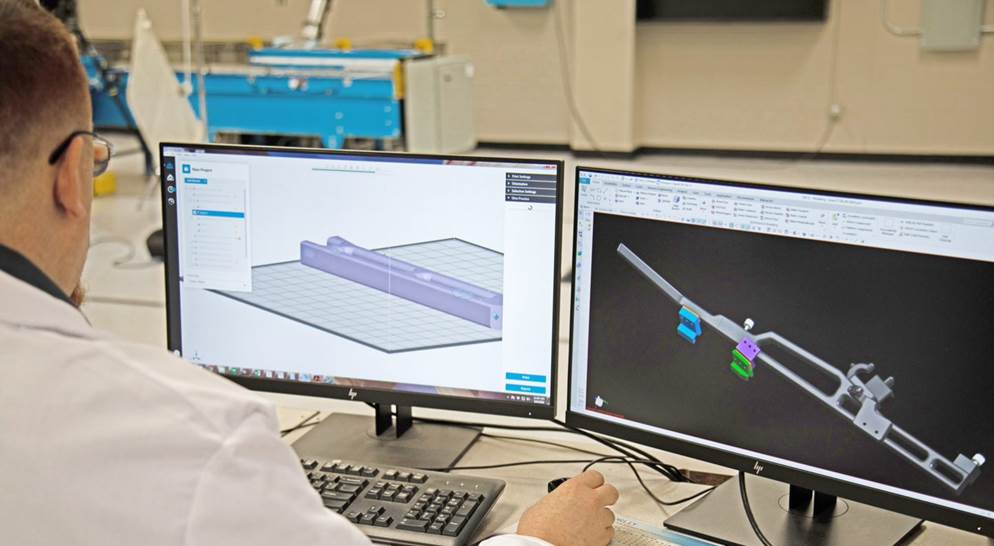
AM requires a different approach for design, fabrication, and validation compared to traditional methods of manufacturing. Designing for Additive Manufacturing (DFAM) is the key to reducing as much cost and lead time without compromising performance for manufacturing tooling. Taking a tool design from CAD to production can often be convoluted due to limitations in the software used to prepare the design to be printed. Enter Jigs and Fixtures for GrabCAD Print, a new advanced FDM processing software which enables the user to meet their use case requirements by adjusting the strength, rigidity and fill style of bodies as well as the faces/surfaces on the part.
1. Body processed with solid infill for added durability.
2. Body processed with solid infill for hole to be tapped during post processing.
3. Face thickened for added tool durability throughout thousands of cycles.
4. Body processed with low density and thickened shell for light-weighting while maintaining structural integrity.
For the first time, designers and engineers have functional control over the part they are building. Users can now locally add thickness to selected faces that may need reinforcement and have region specific density, shell thickness and infill styles. This is useful in situations where parts that need internal reinforcement or added shell thickness, without having to build a completely solid part, leading to reduced material usage, part weight and build times while still maintaining structural and functional integrity.
If you or your company are a Stratasys Customer and would like to learn more about implementing AM in your manufacturing operation click here, or if you could benefit from an improved workflow for developing manufacturing tools like jigs and fixtures, click here.


